DCC vs DC Model Trains: Differences and How to Choose

DCC (Digital Command Control) and DC (direct current) are two different ways of sending electrical power and control signals to a model railroad track: with DC, the controller varies the voltage and polarity on the rails to set a train's speed and direction. In DCC, the track instead carries a digital signal encoded as a bipolar square waveform, and because every locomotive carries its own addressed decoder, several trains can run independently over the same two rails from one controller.
DC vs DCC at a Glance
Digital Command Control is a standardized communication protocol for controlling model railways, built so products from different manufacturers stay compatible with each other, while conventional DC control simply varies the voltage and polarity sent down the rails.
| Point | DC (analog) | DCC (digital) |
|---|---|---|
| Signal on the rails | Level and polarity of the electrical power set a locomotive's speed and direction | A bipolar square waveform carries digital commands together with the power |
| Running several locomotives | A basic set suits a single operator and cannot adequately control multiple trains independently | One command station addresses each decoder individually, so several locomotives run independently from one controller |
| Track wiring for multiple trains | Requires the track to be wired into separate electrical blocks with switches | Block switches are often no longer needed, since each locomotive responds only to its own address |
| Decoder or address needed | Not required | Each locomotive carries an individually addressable digital decoder |
| Governing standard | Not covered by the NMRA DCC standard set | NMRA S-9.1 (electrical) and S-9.2 (communications) |
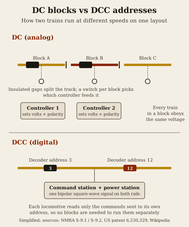
How DC (Analog) Control Sends Power to the Track
Conventional DC control sends electricity through the rails from a controller, and a locomotive's speed and direction follow the level and polarity of that electrical power directly.
A basic DC model railroad set suits a single operator but lacks the capability of adequately controlling multiple trains independently, since every locomotive on a powered section responds to the same voltage and polarity at the same time (US patent 6,530,329). Running two or more trains at different speeds on the same layout therefore means wiring it into separate electrical blocks, each with its own switch to select which controller feeds that section, an approach to planning track covered in our piece on model railroad layout plans.
Hornby launched its Dublo range of OO-scale electric trains in 1938, running on 12-volt DC power over three-rail track with an electrically insulated centre rail, and introduced two-rail track for the range in 1959.

How DCC Sends Power and Commands to the Track
Digital Command Control is a standardized communication protocol for the control of model railways, developed through standards and recommended practices written by the DCC Working Group of the National Model Railroad Association. Its most obvious advantage is that several locomotives on one stretch of track can be run independently. A digital signal is carried inside the electrical waveform that powers them, so there is no need to park locomotives in electrically isolated blocks as analog control requires.
On the rails, every locomotive receives the same electrical signal, but each one responds only to the commands addressed to it, which is why DCC is often said to need "only two wires" (Wikipedia). The NMRA describes this signal as a bipolar square waveform carrying digital information rather than varying DC voltage, with binary data encoded as pulses of different lengths: long pulses represent zero and short pulses represent one.
More precisely, a binary 1 is a square wave with a nominal period of 116 microseconds and a binary 0 one with a nominal period of 200 microseconds. A command station sends roughly 8,000 bits per second, and the signal's frequency varies between about 5 kHz and 9 kHz depending on the data being sent.
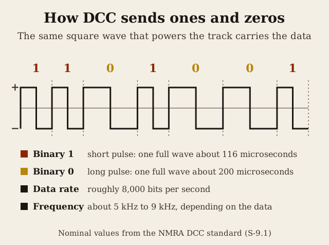
The NMRA specifies the voltage of the DCC signal according to the modelling scale in use, and the power the signal carries is its peak-to-peak voltage multiplied by the current; for the scales themselves, see our guide to model train scales (Wikipedia).
What DCC Adds for Running Several Trains, Sound and Functions
DCC lets one controller run more than one train or accessory at a time, because each decoder has its own address and only reads instructions addressed to that decoder.
A mobile decoder installed in a locomotive controls nearly every aspect of its behavior: direction of travel, speed, lighting effects and sound effects (Wikipedia). Many decoders also include inertia simulation, so a locomotive gradually speeds up or slows down in a realistic way, and constantly adjust motor power to help it maintain a set speed (Wikipedia).

DCC decoders can also drive onboard sound systems and flashing lighting effects such as ditch lights and markers, as many or as few as a modeller wants to install (NMRA). In the 2010s, on-board sound modules arrived for locomotives as small as N scale, made possible by advances in the small, high-quality speakers developed for smartphones (Wikipedia).
Most digital throttles let an operator set one locomotive's speed, then select a different locomotive to control while the first keeps running at its set speed. The NMRA's DCC Working Group later extended the original design so that it can control up to ten thousand locomotives, turnouts and multiple-unit lash-ups.
Accessory or stationary decoders extend the same addressing system to turnouts, signals and animated scenes using basic input and output control built into the decoder (Wikipedia). Wiring requirements are also generally reduced compared with a conventional DC-powered layout, since accessory wiring runs out to distributed accessory decoders instead of back to a central control panel, which on portable, sectional layouts can mean only the digital signal and accessory power supplies need to cross each join between sections (Wikipedia).
Configuration Variables: Customizing a DCC Decoder
Each configuration variable, or CV, holds an 8-bit value that the decoder keeps in non-volatile memory. Programming CVs is the main way a modeller customizes a decoder and adapts it to their own layout.
Modellers commonly use CVs to adjust a decoder's motor response, its voltage-to-speed mapping, lighting effects, function output mapping, sound effects and sound volume, and command stations typically provide a way to program these values directly from a throttle (Wikipedia).
Only four CVs are absolutely standardized, under NMRA S-9.2.2: CV1 for the decoder's address, CV7 for the decoder's version as set by its manufacturer, CV8 for a manufacturer ID assigned by the NMRA, and typically CV29 for basic movement configuration; every other CV is left as a recommended or optional choice for the manufacturer (Wikipedia).

Where DC Stays Simpler
For a small layout with one or two trains, DC block control is simple and straightforward to wire and install, and it needs no decoders or CV programming; on bigger layouts, though, the block wiring task can become immense. A basic DC set suits a single operator but lacks the capability of adequately controlling multiple trains independently, which is the job DCC decoders were designed to do (US patent 6,530,329).
A basic DCC system also needs more coordinated parts just to run: a single command station, at least one power station to amplify current to the rails, one or more throttles, and a decoder in every locomotive, roles that are often bundled into one all-in-one box for an entry-level set but stay as separate components once a layout grows (Wikipedia).

The NMRA Standard Behind DCC
The National Model Railroad Association (NMRA) is a nonprofit founded at its first national convention over Labor Day weekend in 1935, and today advances scale model railroading worldwide through education, advocacy, standards and social interaction for over 16,000 active members, associates, families and clubs. The organization is headquartered in Soddy Daisy, Tennessee.
The NMRA Standards lay down the widest coordinated set of limits on dimensions, electrical parameters and communications parameters; equipment that stays inside them is assured of interchange. DCC itself is defined by two standards, S-9.1 for the electrical side and S-9.2 for communications, plus several recommended practices documents.

Before writing its own standard, the NMRA's DCC Working Group studied the commercially available command-control systems already on the market rather than starting from nothing, and settled on basing the new standard on a system invented by Lenz Elektronik that Märklin was already using for its two-rail sets. Lenz had developed that system in the 1980s under contract for Märklin and Arnold (Wikipedia).
In 2006, Lenz joined with Kühn, Zimo and Tams to develop RailCom, an extension to the DCC protocol that adds a feedback channel from decoders back to the command station, letting the system report which train occupies a section of track or an engine's actual speed; RailCom was standardized in 2007 as NMRA S-9.3.1 (Wikipedia).
Layout command control (LCC), previously called NMRANet, is a separate standard introduced in 2015 to relieve congestion on the DCC communication bus, since the growing use of stationary decoders for automation and animation had begun generating enough packets to crowd that bus; LCC keeps vehicle-control communication on the DCC bus and moves everything else onto a separate LCC bus (Wikipedia).
Points to Weigh When Choosing DC or DCC
Compatibility across brands is a practical first question: DCC does not specify the protocol used between a command station and other components such as additional throttles, so command stations from one vendor are generally not compatible with throttles from another vendor even though the track-level DCC signal itself is standardized.
Several major manufacturers, including Märklin, Fleischmann, Roco, Hornby and Bachmann, sell DCC-compatible products alongside specialists such as Lenz, Digitrax, ESU, ZIMO, Kühn, Tams, NCE, Digikeijs, CVP Products, Sound Traxx, Train Control Systems and ZTC, so choosing DCC also means choosing among competing command-station ecosystems (Wikipedia).
Outside the NMRA's DCC standard, two main European alternatives exist: Selectrix, an open Normen Europäischer Modellbahnen (NEM) standard, and the proprietary Märklin Digital system, while the US Rail-Lynx system instead keeps a fixed voltage on the rails and sends commands digitally using infrared light (Wikipedia).
Weighing DC against DCC in the end comes down to how many trains a modeller plans to run independently, whether sound and lighting effects matter, and how much wiring and CV programming they are willing to take on: DC keeps the wiring and controls minimal, while DCC trades a decoder and some configuration time for independently addressable control of every locomotive and accessory on the layout.

Rails & Rivals, our game on Steam, is a turn-based railroad strategy board game for 2 to 6 players: each player runs a rail company, lays track across a hex map and carries goods between cities, and the wealthiest company wins. The how to play page has the rules.
Keep reading
Sources
- Digital Command Control (DCC) (National Model Railroad Association (NMRA))
- About the NMRA (National Model Railroad Association (NMRA))
- NMRA Standards and Recommended Practices (National Model Railroad Association (NMRA))
- National Model Railroad Association (Wikipedia)
- Digital Command Control (Wikipedia)
- US Patent 6,530,329 - model railroad command control system (Google Patents (USPTO))
- Rail transport modelling (Wikipedia)